1. 单击“框架”(Framework) >  “新建连接器元素”(New Connector Element)。“新建元件”(New Component) 对话框将会打开。
“新建连接器元素”(New Connector Element)。“新建元件”(New Component) 对话框将会打开。“新建连接器元素”(New Connector Element)。“新建元件”(New Component) 对话框将会打开。 以访问库并从 STEEL CONSTRUCTION INCH > AISC 文件夹中选择非标准连接。元素将在预览区域中出现。
类型 | 预览 | 曲面 | 选项 | 值 |
SINGLE SHEAR PLATE | 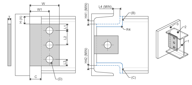 | Profile side face Profile top Attach face | Offset from top Top beam end cope Bottom beam end cope Profile holes | L1, L2, L3 W, W1 C, H L4_MIN H41_MIN H42_MIN R4 |
SHEAR ENDPLATE | 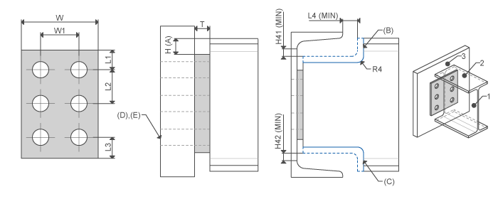 | I-Profile end Attach face | Offset from top Top beam end cope Bottom beam end cope Attach holes thru next Attach holes thru all | L1, L2, L3 W, W1 H L4_MIN H41_MIN H42_MIN R4 |
DOUBLE ANGLES | 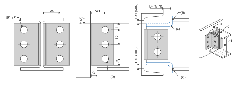 | Profile side face Profile top Attach face | Offset from top Top beam end cope Bottom beam end cope Profile holes Attach holes thru next Attach holes thru all | L1 L2 L3 W W1 C H L4_MIN H41_MIN H42_MIN R4 |
SINGLE ANGLES | 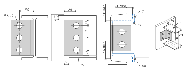 | Profile side face Profile top Attach face | Offset from top Top beam end cope Bottom beam end cope Profile holes Attach holes thru next Attach holes thru all | L1 L2 L3 W W1 C H L4_MIN H41_MIN H42_MIN R4 |